Thursday, November 21, 2013

Safe Delete(Shred) DATA in HDD/ Partition in LINUX


What Happens when you issue remove command on File System?

     Most File System just remove the vnode link from the DIR structure. So what happens to your DATA. You got is right, it just sits at the DISK, waiting for be overwritten or to be recovered by a Crash Recovery Software. The latter sounds good when you are actually using it, but if some one else uses it. You know the consequences. 

How to Safe Delete/ Shred File?

Simple, use any of the above commands

sudo dd if=/dev/zero of=<Device Target>

eg 
sudo dd if=/dev/zero of=/dev/sda

To get the Device Target use the following command

fdisk -l

This command lists all the Disk Partition info with Disk targets.

You can also use this command, if you need to be so sure. This makes two passes in shredding. 

sudo shred -vfz -n 1 <Device Target>

eg
sudo shred -vfz -n 1 /dev/sda

You can also use the LiveBoot of gparted.iso(http://gparted.org/). Boot it via CD/USB. And issue the above command even in Windows/ NON-Linux x86 Machines.

Note : Be careful when playing with these commands. You may purge away useful data Partition/Disk.


Sunday, September 29, 2013

Our Terrace Garden


After much hard work and finally had my first harvest today..


Flowering Plants

Rose


Tomato
 Beans
 Palak
 Palak and Spinach


Thursday, August 22, 2013

POC : Germination on PVC PIPE (Terrace Garden)

Here are the pics. Plants gown here are as follows.
1. Siru Keerai(Tamil) aka Tropical Amaranthus(Botanical)
2. Arai Keerai(Tamil) aka Amaranthus dubius(Botanical)

Added coco peat to get healthier seed germination.


More info to make the PVC structure @
http://ddeepakraja.blogspot.in/2013/05/diy-terrace-garden-from-pvc-pipe.html

Tuesday, July 16, 2013

DIY: Make PCB circuit board at HOME (TONER TRANSFER METHOD)


Bill of Materials
  • Ferrous Chloride (PCB Etching solution)
  • PCB Board
  • Express PCB on PC.  http://www.expresspcb.com/
  • Laser Printer or ( INKJET Printer and Photocopier which uses LASER printers ink)
  • Ordinary Paper
  • Permanent Marker PEN
  • Hot Iron box
  • Kitchen Dish wash bar (VIM dish cleaning bar)
  • Scrub Pad
  • Tissue Paper
  • Paint Thinner Solution
  • 0.1''(inch) drill bit and 0.08"(inch) drill bit
  • Hand Held Driller/ Motorized Driller.
Caution : You are gonna play with Industry Grade Corrosive Solutions. Wear Eye Glasses and protecting gloves before working on this.

1. DESIGN OF PCB CIRCUIT
You need Express PCB software at http://www.expresspcb.com/
PCB components
Pad - The portion of the conductive pattern on printed circuits designated for the mounting or attachment of components. Also called land.
Traces - Literal wire for connecting pads and nodes.
A width of 0.010" is a good default for digital and analog signals.  For power lines, use traces 0.05" or wider.
LAYERS of PCB board
Red -- Top copper layer selection
Green -- Bottom copper layer selection
Yellow - Top silk layer

Start designing the circuit and finalize the design.

2. PRINT OUT the circuit (Toner Transfer Method)
Issue a print out on the Laser Printer. Make sure to make darkened printout. This can be done by changing the printer darken properties. If you happen to have Inkjet printer make sure to print the circuit and obtain a photocopy on photocopier with LASER printer INK. Make sure to darken the copy Image too.

Note: You may/may not need to mirror the circuit image before printing out the circuit on the paper. This step may be need as per your design of the circuit. 

Note: Laser Printer Uses TONER INK. Any printing device using TONER INK is sufficient.

My Printout of the circuit. If you have multi layered  PCB(usually 2 layered). Make sure to take one printout for each layer. I went with single layered PCB only.


3. PCB Cleaning
Wash the PCB Kitchen Dish wash bar (VIM dish cleaning bar or any alternate). Make sure to use the scrubber pad and remove all the oily residue attached on the top of the PCB. Wash with water. Wipe it with dry Tissue. Don't ever touch the Copper side. Your touch places oil back on the PCB.

4. IRON Out the Circuit to the PCB
Make sure to place the circuit print on the copper side and fold out the rest of the paper around the PCB. Use of Sticking tape is not encouraged, as Tape tends to melt out when heat is applied. Apply the Hot IRON on the Paper. Make sure to apply heat uniformly across all the sections of the circuit. Keep the heat and press on the paper for minimum of 10 minutes.

Caution : You are playing with HOT IRON. You may get burns if not used properly. Entire PCB board with the Paper on top will be so hot to hold.


5. CIRCUIT on PCB
After hot iron, give some time to cool out. You will now notice that the CIRCUIT INK melted and stuck to the PCB board. Immerse, the PCB into water and start peeling of the paper. You get the Circuit on the PCB.


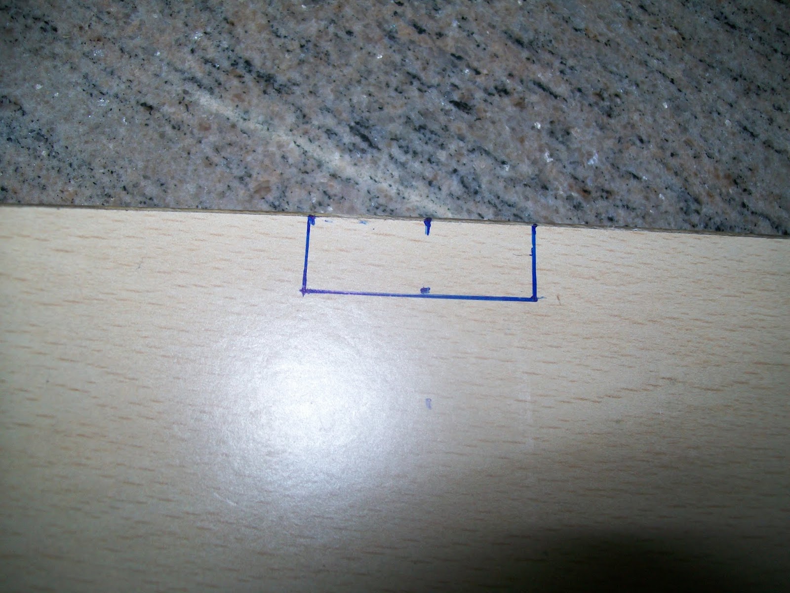
6. CORRECTION on PCB circuitry (if any)
You can use the Permanent Board marker to sketch up the left over circuit traces.


7. FERROUS CHLORIDE (the Magic Solution)
Make sure to read the instructions on the solution pack. Usually this chemical comes as a power form. You need to make sure to follow the instructions given in the pack to make the liquid form(Mix with water). Ferrous chloride eats away any exposed metals which comes in contact. Even its vapor is corrosive. Tie the PCB to a Plastic wire and lower it into Ferrous Chloride, which is contained inside a Plastic box. Ferrous Cloride can't attack Plastic. Never touch the solution on bare hands. If happened to touch it accidentally, wash it thoroughly on soap and running water.

Caution : You are gonna play with Industry Grade Corrosive Solutions. Wear Eye Glasses and protecting gloves before working on this.


Make sure to shake the container often, so that the solution is spread out evenly. Generally, it takes less than 20 minutes to etch the metal fully. You have to take out the PCB with the tied wire to check this.

8. PCB Cleaning
Once all the exposed metal are etched away. Dip the PCB in water. Use Kitchen disk wash bar and Scrubber pad to clean the TONER INK. You can also try Thinner solution on the PCB to remove TONNER INK.


10 . FINAL PRODUCT


Note : You have to use the Driller to punch hole for the components mount pads. 


Thursday, May 30, 2013

X11 Forwarding in UBUNTU/ debian

Most Linux Servers are hosted under datacenters. Console SSH access are too dull in aiding USER INTERACTION. GUI can be accessed via SSH + X11 Forwarding. Below are the steps to achieve the same.

1. Download Xming Server for Windows @ http://sourceforge.net/projects/xming/
2. Install Xming Server. Launch Xlaunch and Select MultiWindow option and Display port as 0
3. Launch Putty. Make sure to close all the older putty sessions and relaunch it. Under SSH section -> X11 forwarding Enable it. Display Location as localhost:0
4. Save the session after specifying ServerIP and other details.
5. Login into the Server via SSH from PUTTY.
6. Check if the DISPLAY is set. Don't care about the value for the $DISPLAY variable.
$ echo $DISPLAY
localhost:10.0
7. Install X11 packages under UBUNTU/debian.
$sudo apt-get install xorg
7. Test it. Now you should see a clock window in you windows box. 
$ xclock


Monday, May 20, 2013

COMPUTER AIRFLOW/ CHASSIS FAN DESIGNING DEMYSTIFIED

Had setup a server at home. Did some research on the AIRFLOW in and out of the CHASSIS.

TIPS 
  1. BIGGER FAN(120MM with 1200RPM) controls temperature better.
  2. BETTER CABINET from GOOD Vendor gives added advantage. You may get inbuilt FAN with CHASSIS.
  3. LOOK for LAWS/RULES governing HEAT transfer. Click here for Rules : http://www.techpowerup.com/forums/showthread.php?t=42853
  4. BETTER to control the FAN/ POWER connection via MOTHERBOARD. Best to AVOID straight connection to FAN from SMPS. Straight connection makes the FAN NOISY and reduces the LIFE OF FAN.
  5. FIND the direction of AIR FLOW at the CPU FAN(4pin) which is controlled by Motherboard.
  6. FIND the direction of AIR FLOW at the GPU/VGA/Graphics Card at PCI/PCIe/PCI2.0 slots. This card may contain INBUILT FAN. IF so check the AIR FLOW direction.

Finding AIR FLOW DIRECTION http://www.youtube.com/watch?v=wlgfAO2Jtls
Also to find AIR FLOW direction, place a piece of paper near the FAN. If it sucks in then AIR IN and expels then AIR OUT.

Does 3PIN FAN connector fits into 4 PIN MOTHERBOARD??? YES. Make sure to connect the GND to BLACK WIRE FROM FAN. 4th PIN is for PMW(Pulse Width Modulation), which is used to control RPM on the FLY from UEFI BIOS/ SOFTWARE from OS. JUST 3 PIN FAN also works by leaving PWM PIN. More Info : http://hardforum.com/showthread.php?t=1692017

MY CHASSIS AIRFLOW DESIGN (Best I can GET FROM TRIAL and ERROR Method)


AIR IN - ONE FRONT BOTTOM, TWO SIDE PANEL
AIR OUT - REAR TOP, SMPS TOP FAN
CPU FAN - SUCKS AIR INTO HEAT SINK

MY COMPUTER CHASIS AIR FLOW

UEFI BIOS REPORTS TEMPERATURE AND FAN SPEED

CONCLUSION : ONLY THIS SETUP GAVE BEST RESULTS (ie TEMPERATURE DIFFERENCE OF Approx 5 deg centigrade lesser if compared with OTHER SETUPs).


DIY : Computer Server CHASSIS Table / Multipurpose Table

Had happened to build a multipurpose table to host my computer CHASSIS and Printer. Started working on and built one. Added space for hosting two rows to hold more ITEMS.

BILL OF MATERIALS AND DESIGN
PLYWOOD, REEPER

 PLYWOOD horizontal TOP ROW upside down
 PLYWOOD horizontal TOP ROW upside down with SMALL 3* REEPER nailed.
Marking for the L shaped metal grippers on both horizontal (TOP and BOTTOM) Plywood.


 L shaped metal grippers screwed on to both VERTICAL (LEFT and RIGHT) Plywood.
Center cut at the BOTTOM HORIZONTAL PLYWOOD


SCREW IT UP FRONT VIEW
 UPSIDE DOWN VIEW
Additional Stability by NAILING


Adding a BIG REEPER in the MIDDLE of the FRAME(ADDS RIGIDITY/ STABILITY). BACK VIEW
 FULLY LOADED. TESTED with 2 MEN occupying TOP row.